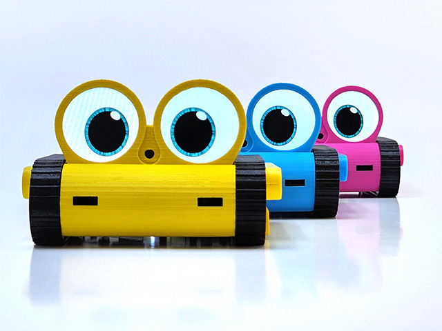
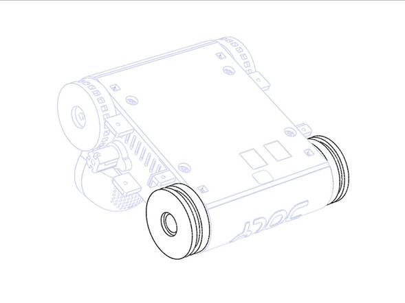
Doly Maker Edition Build Guide
A step-by-step manual for building a 3D-printable Doly robot at home.
Safety & Disclaimers
- ❗ Battery safety : Never short terminals. Charge with only Doly charger after assembly is completed on a non-flammable surface.
- ❗ Small parts : Choking hazard; keep away from children. This kit is not a toy and is intended for competent hobbyists.
- ❗ Tools: Wear eye protection when cutting/filing. Be cautious, especially using sharp cutters, if needed.
- ❗ Electrostatic discharge : Ground yourself before handling electronic boards.
- ❗ Ventilation : Print and glue in ventilated spaces; follow material manufacturers guidance.
- ❗ Always verify polarity and connector orientation before plugging the battery.
Project overview
- Doly Maker Edition : Doly is a AI-powered companion robot, with this project you will 3D‑print Doly robot body parts and assemble the robot.
- Electronic Boards: Raspberry Pi CM4 compatible mainboard, head PCB with LCDs, bumper PCB including ToF proximity sensors, and microphones, arm PCBs for hand RGB LEDs and I/O PCB.
- 3D‑print Material : PETG or PLA.
- What youll do : 3D‑print → post-process → sub-assemblies → wiring → assembly → testing.
Required 3D‑printed parts
You could access the full list of parts from our GitHub /Printables/PLA-PETG folder.
https://github.com/robotdoly/DOLY-DIY/tree/main/Printables/PLA-PETGHardware & electronics
- [E01] Main board (Raspberry Pi CM4-based)
- [E02] Head PCB (with LCDs, touch sensors and camera)
- [E03] Arm PCBs (2 pcs)
- [E04] Bumper PCB
- [E05] I/O PCB
- [E06] Li-ion Battery
- [E07] Motor with 8-pin FPC cable (Left)
- [E08] Motor with 8-pin FPC cable (Right)
- [E09] Servo (Left)
- [E10] Servo (Right)
- [E11] Speakers (2pcs)
- [E12] Fan
- [C01] 45-pin FPC cable
- [C02] 12‑pin FPC
- [C03] 24-pin FPC
- [S01] M1.6 x 3mm countersunk machine screws (4 pcs)
- [S02] M1.7 x 3mm washer‑head self‑tapping screw
- [S03] M1.7 x 7mm round‑head self‑tapping screw
- [S04] M2 x 4mm countersunk self‑tapping screws (10 pcs)
- [S05] M2 x 6 mm countersunk self‑tapping screws (2 pcs)
- [S06] M2 x 18 mm countersunk self‑tapping screws (2 pcs)
- [S07] M2 x 5mm round‑head self‑tapping screws (6 pcs)
- [S08] M2 x 10mm round‑head self‑tapping screws (2 pcs)
- [S09] M2.3 x 14 pan‑head self‑tapping screws (2 pcs)
- [H01] M2.5 x 8mm hex spacer (2 pcs)
- [H02] L8 x W8 mm round Stainless-Steel cap (2 pcs)
- [H03] Stainless-Steel tweezers
- [H04] Foam with self-adhesive tape
- [H05] IR Filters (2 pcs)
- [R01] Tracks (2 pcs)
- [R02] Plastic bottom cover with power button
- [R03] Plastic hand with magnet (Left)
- [R04] Plastic hand with magnet (Right)
- [R05] Charging Station with electronics
- [R06] MicroSD card (ready to use)
Print settings
These settings can differ based on your 3D printer.
Note: We are not 3D‑printing experts; adjust as needed. The following are baseline settings that work for us.
- Nozzle : 0.4 mm
- Walls : 3 (≥1.2 mm)
- Layer Height : 0.1 mm for better quality and accurate dimensions
- Infill : 2030%
- Temperature: Follow your filament manufacturer's guidance.
- Supports: Tree supports work well on most parts
- Material: PLA works well for most body parts, but may deform over time on the bottom cover due to processor heat. PETG performs better there. We strongly recommend using the original ABS+PC bottom cover included with your robot. You can print the other body parts with your preferred filament.
Folder & File Organization (GitHub repo)
Step-by-step Assembly
Step 0 Prep & quality checks
- Remove all parts from the package.
- Verify all parts and electronics.
- Unscrew the two screws from the bottom of the semi‑assembled unit. Remove the bottom cover, then the main PCB and battery. (Required for shipping regulations.)
- Keep the bottom plastic cover with the power button [P02].
- Watch the assembly video.
Step 1 3D‑print body parts
- 3D‑print the parts listed below from the GitHub folder.
- Verify all printed parts match quantities and dimensions.
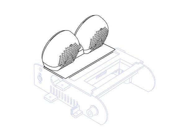
-
Sand/trim where necessary, especially at the pointed locations shown in the image.
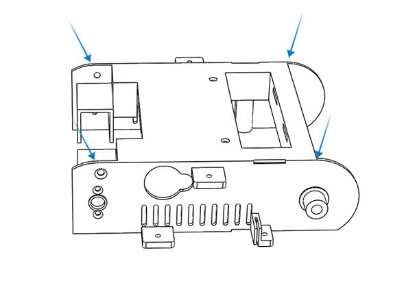
🧱 Parts: Aligner, arm x 2, body, arm_cover x 2, bottom_cover , bumper_back , bumper_front , head, servo_cover , side_cover_left , side_cover_right , Wheel_back x 2, Wheel_front x 2
Step 2 Gluing Body Parts
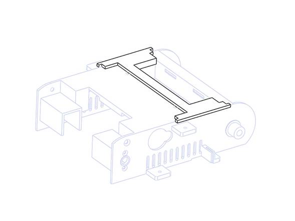
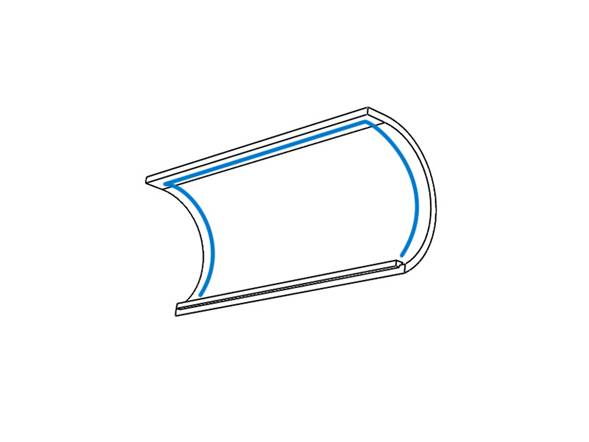
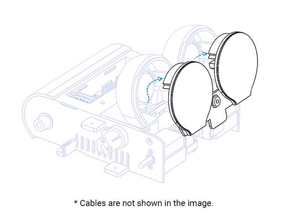
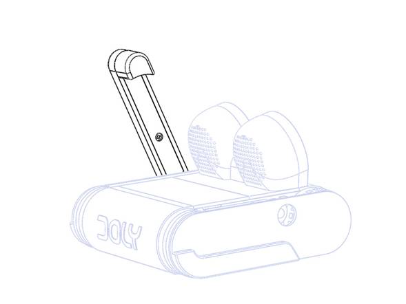
- Before gluing, ensure your print quality is good and parts fit together properly. Pay special attention that servos and motors fit well (see Steps 3 and 4). If you discover an issue after gluing, you may need to re‑print those parts. If you have snapped the servos in and need to remove one, use the linked image as a reference.
-
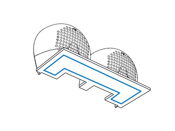
Place the aligner part to the top as shown in the image.
-
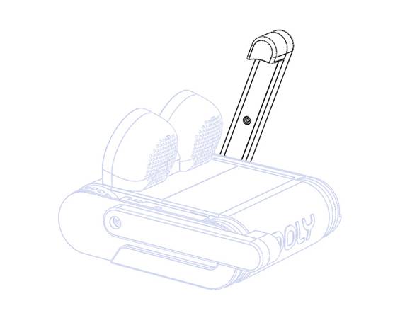
Check alignment and then apply super glue to the bottom of head part as shown in the following image.
-
Then secure as shown in the following image.
- Let it dry for a few minutes.
-
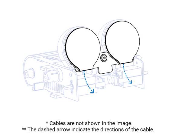
Check the alignment, and then apply super glue to the three contact locations of bumper_back part as shown in the image.
-
Then secure as shown in the following image and hold for a short time.
-
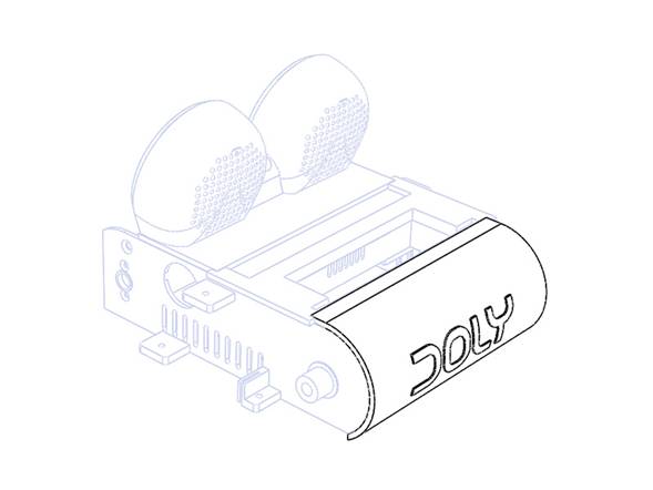
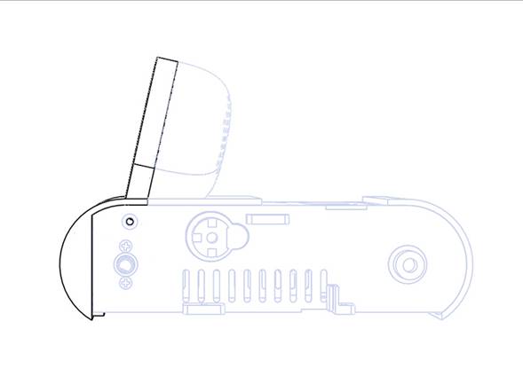
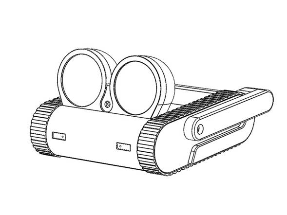
Remove the aligner. After both glue cured you should have a full body as shown in the following image.
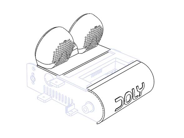
🧱 Parts: Aligner, body, head, bumper_back
Step 3 Servo installation
- Pick servo [E09] (left‑side, labeled L) and insert it into the body housing as shown.
-
Then push to snap it into place as shown.
- If the parts do not fit properly, check the housing print quality. If you see plastic residue or uneven surfaces, carefully trim with a hobby knife and try again.
-
Repeat for the right‑side [E10] and make sure both servos snap into place as shown.
🧱 Parts: [E09], [E10], full_body
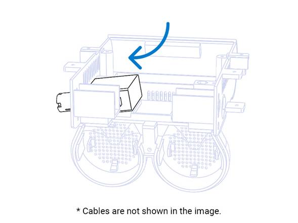
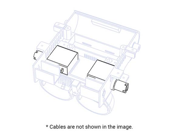
Step 4 Motor Installation
-
Pick motor [E08] (right‑side, labeled R), place it into the housing as shown, and secure it using machine screws [S01].
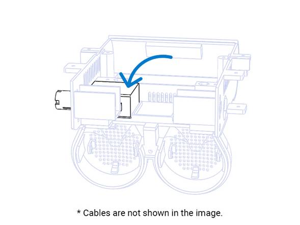
-
Repeat for the left‑side motor [E07] and secure with screws [S01].
🧱 Parts: [E07], [E08], [S01] x 4, full_body
Step 5 Installing Speakers
-
Snap the speakers [E11] into the head housing as shown, ensuring the cable orientation matches the image.
- If the parts do not fit properly check the location print quality. If you see plastic residue or uneven surfaces, carefully trim with a hobby knife and try again.
-
Due to limitations of 3D‑printed material, the speaker holders may not work or may break in some cases during installation. If needed, use a glue gun to apply a small amount of hot glue to the top and bottom to secure the speaker.
🧱 Parts: [E11] x 2, full_body
Step 6 Battery Foam Installation
- Peel the protective film from the foam [H04]
-
Align the foam tape [H04] to the bottom‑center of the back bumper and press firmly to adhere.
🧱 Parts: [H04], full_body
Step 7 Battery Installation
-
Push the battery [E06] into position as shown.
🧱 Parts: [E06], full_body
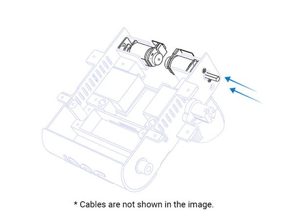
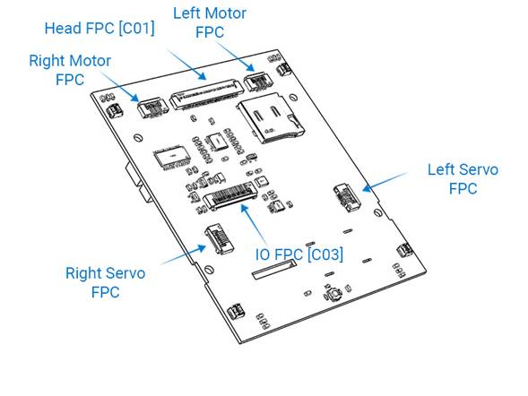
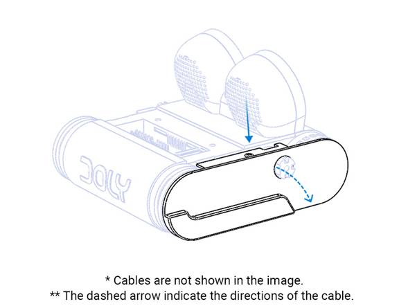
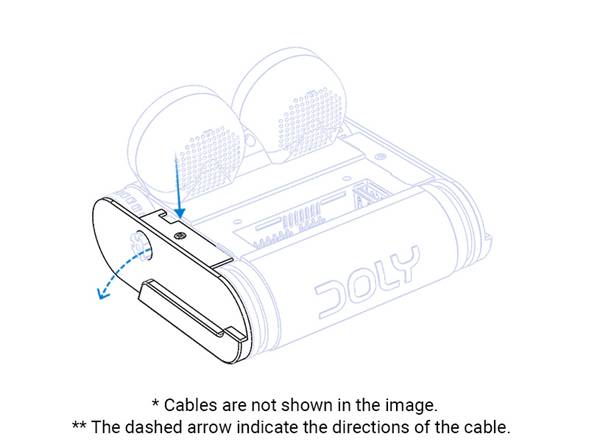
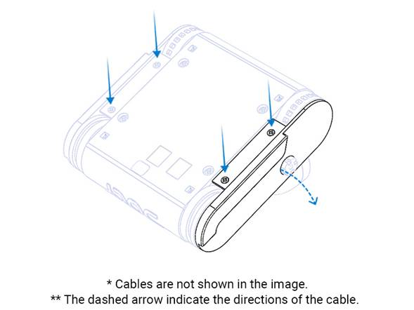
Step 8 I/O PCB Installation
- Open the FPC connectors black latch, gently lift it up, and insert FPC cable [C03] with the metal contacts facing down; close the latch to secure it.
- Bend cable [C03] upward near the connector to aid positioning.
-
Place the PCB [E05] as shown in the image and secure with screws [S07] .
🧱 Parts: [C03], [E05], [S07] x 4, full_body
Step 9 Fan Installation
- Place the servo cover part as shown in the image and secure the fan [E12] to the part with screws [S08] .
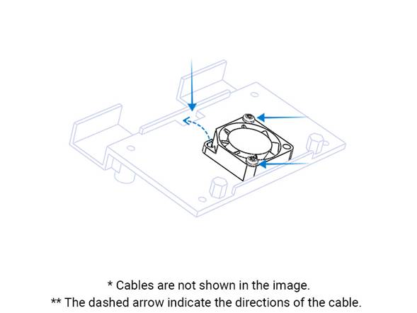
- Route the fan cable through the shown hole to the other side.
🧱 Parts: [E12], [S08] x 2, servo_cover
Step 10 Servo Cover Installation
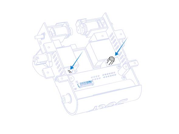
- Place the hex spacers [H01] into the housing as shown.
- Route the servo cables through the hole to the other side.
- Secure previously prepared servo cover part to its location with screws [S07] as shown in the image.
🧱 Parts: [H01] x 2, [S07] x 2, servo_cover
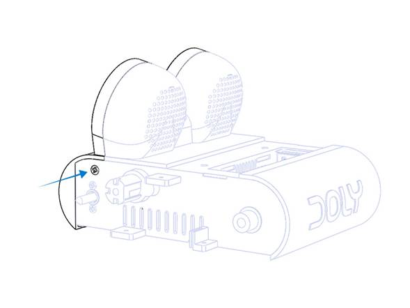
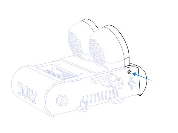
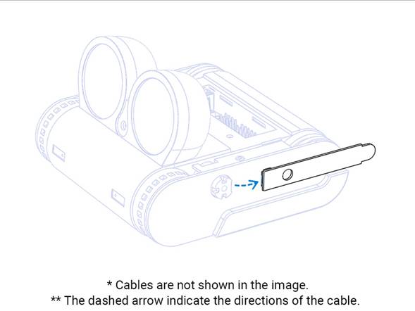
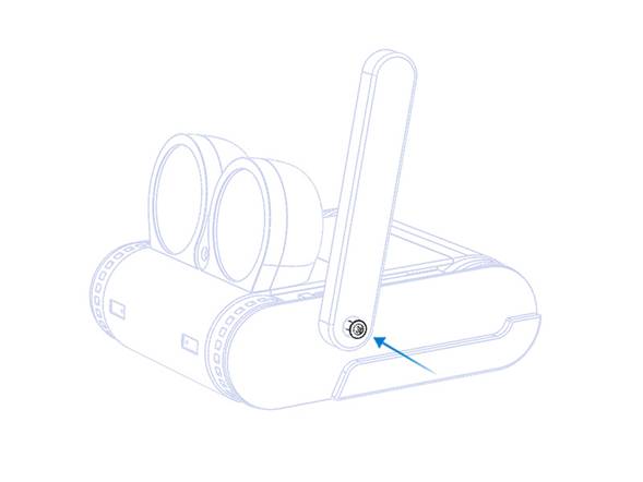
Step 11 Front Bumper Sub-assembly
- Place the IR filters [H05] into their housings as shown.
- Secure the bumper PCB [E04] with screw [S02] as shown.
🧱 Parts: [E04], [H05] x 2 , [S02], bumper_front
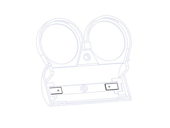
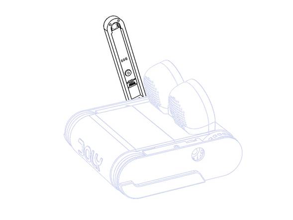
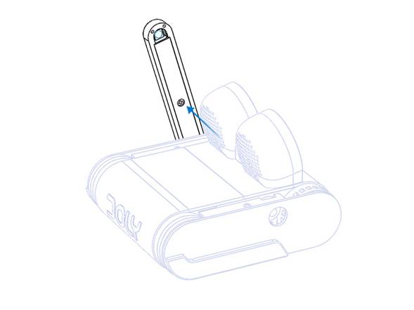
Step 12 Head PCB Installation
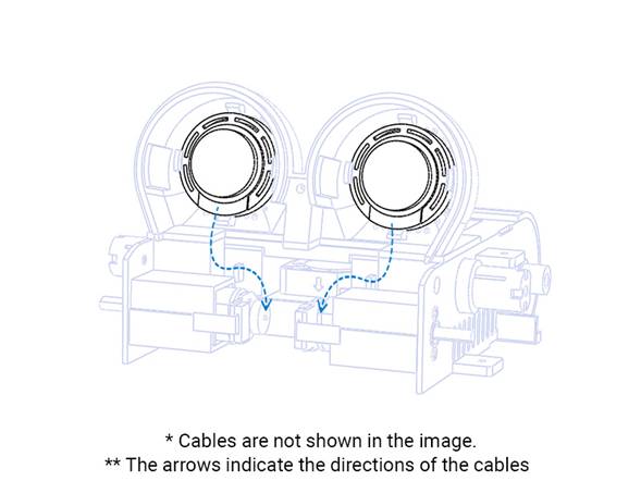
- On the head PCB [E02], open the 45‑pin FPC connectors black latch, insert FPC cable [C01] with contacts facing down, and close the latch to secure it.
- Repeat for the shown 12‑pin FPC connector and secure cable [C02].
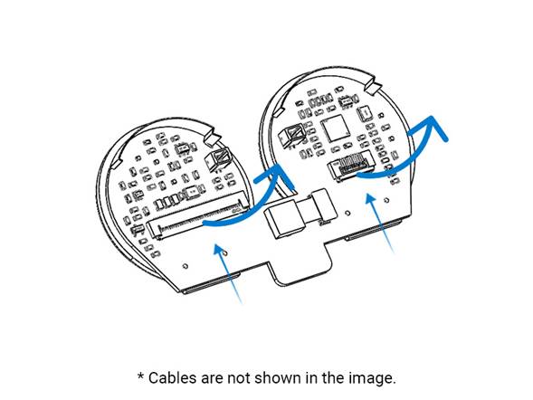
- Move the part close to the body and plug in the speaker cables before positioning it.
- To place [E02], gently press on the touch contacts at the top side of the part. Insert the module starting from the top and working toward the bottom.
- After a proper installation the module should look like the following image. FPC cables are not shown in the image but must be installed.
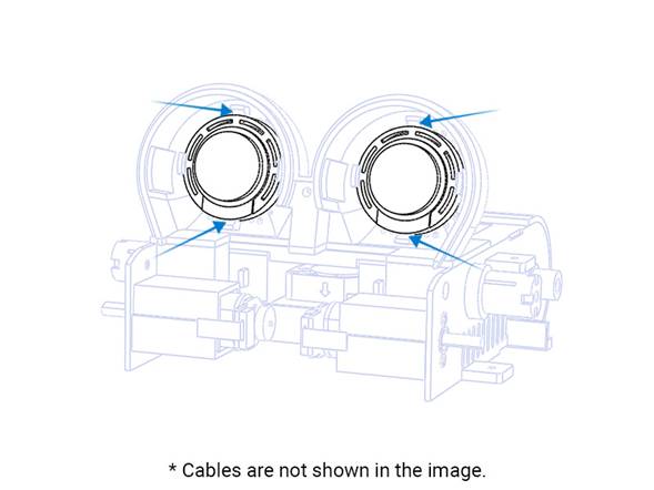
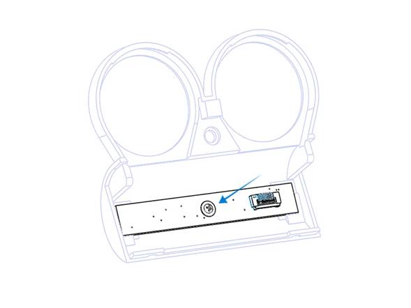
- Now you have to secure head module with front bumper. But before that you have to link Head PCB [E02] and bumper PCB [E04] using the FPC cable [C02]. Open the connector located at bumper PCB [E04] and secure it as mentioned above. Using tweezers while inserting the FPC cable makes this easier.
- Securing the head module with the front bumper requires attention and patience. Check all cables and camera positioned well before application. Place the bumper_front as shown in the following image. As shown, starting from the top and working to the bottom makes things easier.
- After proper positioning the parts should be as shown in the following image.
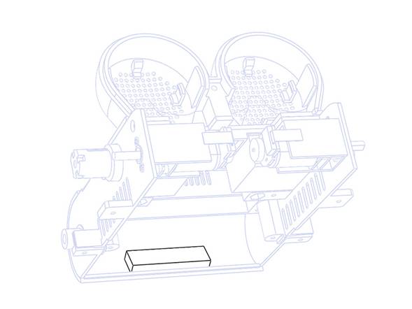
- Now secure the parts with screw [S04] from both sides as shown in the images.
🧱 Parts: [E02], [E04], [C01], [C02], [S04] x 2, bumper_front
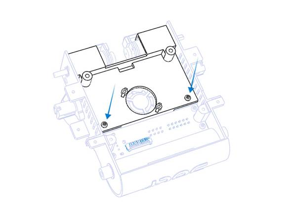
Step 13 Main Board Installation
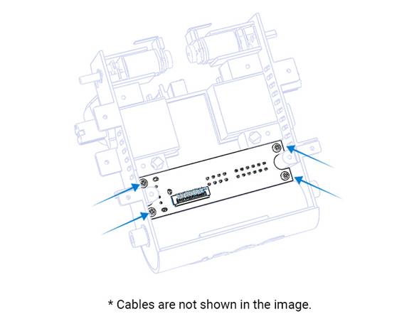
- Before starting, check main PCB [E01] to ensure a Raspberry Pi is installed . If you purchased one from us it comes installed; otherwise install a compatible CM4 module before proceeding. See the FAQ at doly.ai for compatible models.
- There are multiple connectors on both sides of PCB [E01]; connect each cable to its proper location. Please check following images for guidance.
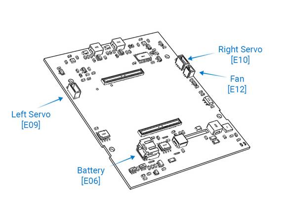
- Plug the battery [E06] socket to the battery connector located at main PCB [E01]
- Plug the left servos [E09] socket to the proper connector located at main PCB [E01]
- Plug the right servos [E10] socket to the proper connector located at main PCB [E01]
- Plug the fans [E12] socket to the proper connector located at main PCB [E01]
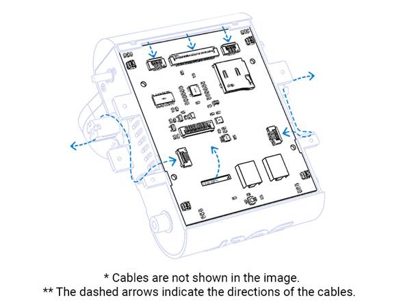
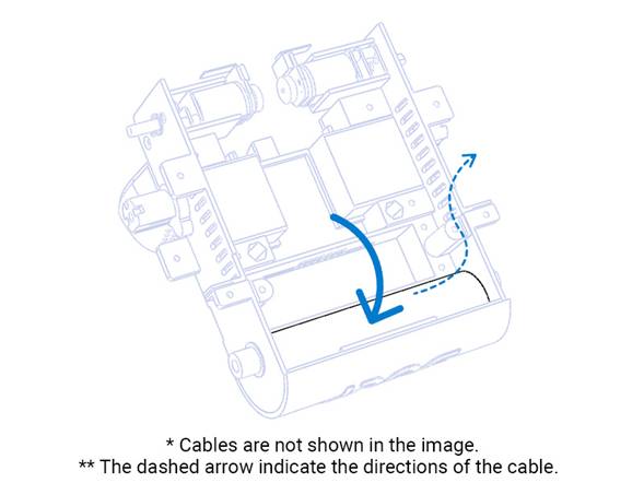
- Place the main PCB [E01] as shown. Dont forget to route [C03] to the other side.
- Secure the motors [E07] , [E08] FPC cables to the proper connector located at main PCB [E01]
- Secure the head module FPC cable [C01] to the proper connector located at main PCB [E01]
- Secure I/O FPC cable [C03] to the proper connector located at main PCB [E01]
- Secure arm FPC cable from left servo to the proper connector located at main PCB [E01]
- Secure arm FPC cable from right servo to the proper connector located at main PCB [E01]
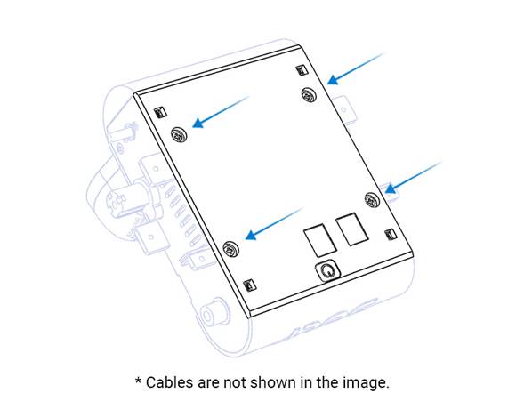
- After completing the wiring, close the bottom cover and secure all parts as shown. We strongly recommend using the injection‑molded bottom cover with the power button; CPU heat can make 3D‑printed bottom covers warp.
🧱 Parts: [E01], [E06], [E07], [E08], [E09], [E10], [E12], [C01], [C03], bottom_cover
Step 14 Wheels Installation
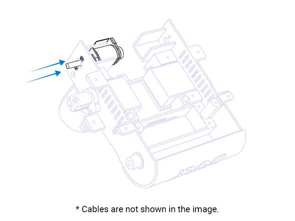
- Align and push the front wheels onto the D‑shafts of motors [E07], [E08] as shown.
- Push the metal cap [H02] onto the rear 3D‑printed shafts on both sides.
- If the parts do not fit properly, check the print quality at that location. If you see any plastic residue or an uneven surface, try to fix it with a hobby knife or sandpaper and try again.
- Align and place the rear wheels onto the metal cap as shown. The rear wheels should rotate freely.
- Before securing the right‑side cover, ensure the FPC cable is routed through the hole to the other side and is not twisted.
- Secure the right‑side cover with screws [S04] as shown in the images.
- Secure the left‑side cover with screws [S04] as in the previous step. Again, ensure the FPC cable is routed through the hole and is not twisted.
🧱 Parts: [E07], [E08], [H02] x 2, [S04] x 6, side_cover_right , side_cover_left
Step 15 Arm Installation
- Connect FPC cable coming from the servo to the arm PCB [E03] connector as shown in the image.
- Remove the temporary screw located at the servo shaft. This screw will not be used anymore; it only keeps the calibrated shaft in the correct position. Do NOT remove the servo shaftonly the screw. If you remove the shaft accidentally, do not follow the next steps. Complete these steps after the servo shaft is re‑positioned. See Troubleshooting for details.
- Align and connect arm part with servo shaft and secure with screw [S09] .
- Now place the PCB [E03] to the arm module. This part of the assembly requires extra attention and patience. Do not pull the FPC cables; they can pop out of the connectors. Be patient and careful at this stage.
- Close the arm with the cover part as shown in the following image and secure both parts with screw [S04] as shown in the image.
- Snap hand [R03] onto the arm with light pressure as shown. Before that, ensure all 3D‑print support material is removed. If fit is poor due to print quality, you may use a small amount of super glue to secure the parts.
- 7. Repeat the same procedure for the other part to complete as shown in the following image.
🧱 Parts: , [E03], [R03], [R04] [S04]x 2,[ S09] x 2, arm, arm_cover
Step 16 Attaching tracks and Final test
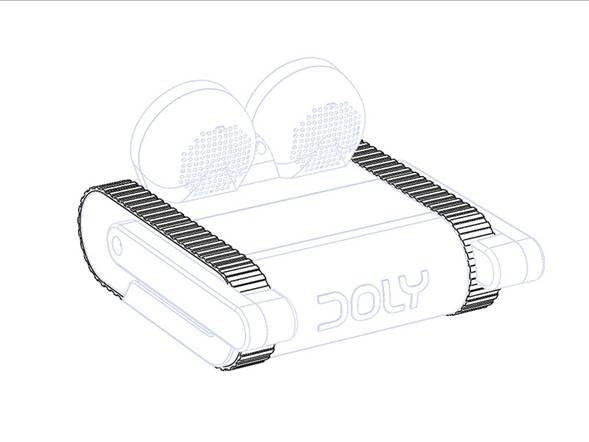
-
Attach the tracks [R01] .
-
Perform a visual inspection before testing.
- Run an arm movement test and let them rotate from end to end. If the FPC cables are connected correctly, movement should be smooth throughout. If the arms do not move smoothly, return to the relevant steps and check that the procedure was completed correctly.
- Start the robot with the power button located on the bottom.
- To shut down after startup, press the button twice within one second to start the shutdown process.
- To force a shutdown, press and hold the power button for more than 8 seconds. Important: Forcing a shutdown may damage the software; avoid doing this frequently.
Troubleshooting
| Symptom | Likely cause | Fix |
|---|---|---|
| LCD black | FPC not seated / wrong orientation | Reseat, check latch; verify backlight power |
| Wont power on | Battery wiring issues / empty battery | Charge battery; check battery connector |
| Continuous blue light at power button | Missing SD card / damaged SD card | Reseat the SD card; replace it and reinstall if needed |
| Removed servo shaft | Accidentally removed | Complete the assembly without arms, start Doly, say Hey Doly, hands up, then after the movement sound say Hey Doly, hands down, and shut down the robot. After that, plug the servo shaft in carefully, aligning the flat side toward the back of the robot. Then re‑follow Step 15. |
| Overheating | Short circuit / wrong polarity | Power down and inspect the harness |
Licensing & Credits
- All files and documentation are licensed under CC BY-NC-SA 4.0 except the software.
- You may not copy, distribute, sell, sublicense, or modify the software.
© 2026 Limitbit. All rights reserved. Doly and associated names, logos, and assets are owned by Limitbit .